
What you need to know about electric bike controller
What is an electric bike controller?
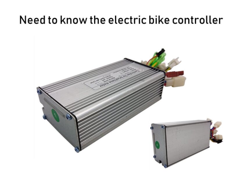
The electric bike controller is one of the main parts of an electric bike, it is the brain of the e-bike, controlling the motor’s speed, start, stop. It is connected to all the other electronic parts such as the battery, motor, and the throttle(accelerator), display(speedometer), PAS or other speed sensors if exist.
A controller is composed of main chips ( microcontrollers) and peripheral components ( resistors, sensors, MOSFET, etc ). Generally, there are PWM generator circuit, AD circuit, power circuit, power device driver circuit, signal acquisition and processing circuit, over-current and under-voltage protection circuit inside the controller.

How does the electric bike controller work?

After connecting the battery, the controller supplies the working voltage to the external device through the power circuit, such as the switch +5V, headlight + 5V, etc.
The PWM outputs a corresponding pulse waveform to the MOSFET drive circuit based on the input of the throttle or PAS. The MOSFET drive circuit controls the turn-on and turn-off of the MOSFET circuit to control the motor speed.
The under-voltage circuit is to protect the battery from discharging when the voltage is lower than the controller set value, at this time the PWM circuit stops the output.
The over-current protection circuit limits the working of the controller, battery, motor at an over higher current.

What is the function of an electric bike controller?
The core function of an electric bike controller is to take all the inputs from all the electric components ( throttle, speed sensor, display, battery, motor, etc.) and then determine what should be signaled in return to them (motor, battery, display).
Other multiple protection functions of the controller will be different from the controller's design. Following are some basic protection functions.
1) Over-voltage protection. The controller monitors the battery voltage and shut down the motor when the battery voltage is too high. This protects the battery from over-charge.
2) Low-voltage protection. The controller monitors the battery voltage and shut down the motor when the battery voltage is too low. This protects the battery from over-discharge.
3) Over-temperature protection. The controller monitors the temperature of the FET( field-effect transistor) and shut down the motor if they become too hot. This protects the FET power transistors.
4) Over-current protection. reduce the current to the motor if too much current is being supplied. this protects both the motor and the FET power transistors.
5) Brake protection. The motor shut down when braking even though other signals taken by the controller at the same time. For example, if the user applies brake and throttle at the same time, the brake function wins.
How to choose the electric bike controller?
The controller should be chosen to fit the other parts- motor, battery, display, etc.
The following factors would be considered.
1. The controller driving type- is it a sine wave or square wave controller?
Sine wave controller advantage:
(1) lower noise.
(2) Higher motor efficiency when climbing or with a heavy load.
(3) Sine Wave controllers have a much smoother and more predictable control of all the operation.
Sine wave controller disadvantage:
(1) Higher price.
(2) Works with the matched motors only.
(3) Higher power consumption.
Square wave controller advantage:
(1) Lower price
(2) Works with different motors
(3) Higher efficiency at sudden accelerate or brake
(4) Higher utilization of the power voltage
Square wave controller disadvantage:
(1) Bigger noise.
(2) The control is not linear, not smooth, and punched sometimes.
(3) Lower motor efficiency when climbing or with a heavy load.

2. Is it a Hall sensor drive or non-Hall-sensor or dual mode controller?
Generally, if a motor has hall sensors, the controller should be hall-sensor or dual mode. Hall sensor in the motor will sense the motor rotation, and the controller will output the corresponding voltage to the motor according to the sensor signals. It is more stable, with lower power consumption and bigger start torque. When the motor hall sensor damaged, the hall-sensor controller may prompt error and stop work while a dual mode controller works well.
3. The controller Voltage- 24V or 36V or 48V or 60V or others?
The controller voltage should match the voltage of the motor and the battery.
4. The controller current( rated current and max current)
The controller current should be smaller than the battery output current.
Generally, the max current is 18A for a 6-MOSFET controller, 25A for a 9-MOSFET controller, 35A for a 12- MOSFET controller, 40A for a 15- MOSFET controller, 50A for a 18- MOSFET controller.
5. Controller functions
How to connect the electric bike controller?
The wire types and wire terminal(connector) of the e-bike controller could be different in the different controller design. You need the electric bike controller wiring diagram to ensure the right wiring connections.
Most e-bike controller will have these wires motor, battery, brakes, throttle/ accelerator or PAS Pedal Assist System (some controllers have both types of wires, some have one of them).
Some more wires are found in the advanced controllers, such as Display or speedometer, Three speeds, Reverse, LED light, etc.
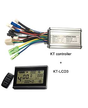
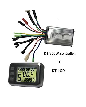
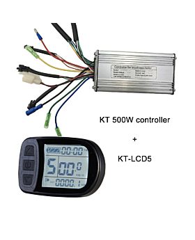
Here is one KT controller wiring diagram.


Sign In
Create New Account